

Optimizing Network Performance for LTE and Beyond
Identifying PIM and localizing the offending components can be difficult. Telltale symptoms, such as an increased noise floor at the base receiver, increased uplink interference, lower SNR, reduced service area, or even a higher rate of dropped calls or low data throughput, can masquerade as an under-performing system.
Every component in the RF path has the potential to contribute to PIM. Common causes include surface oxidation, loose metal-to-metal contacts, improperly torqued connections, objects close to cell sites, contact between dissimilar metals, and surface contaminants such as solder splatters.
As you begin to tackle the issue of PIM in your network, it’s important to take a system-wide approach to solving this pervasive challenge. By definition, PIM is a system issue because it takes one passive component and two or more frequencies in the RF path to create an unwanted signal. That means it’s important to embrace a comprehensive and proactive strategy for addressing PIM instead of waiting for network testing to indicate a problem. PIM problems can be addressed proactively by ensuring high-quality, positive connections between components, for example.
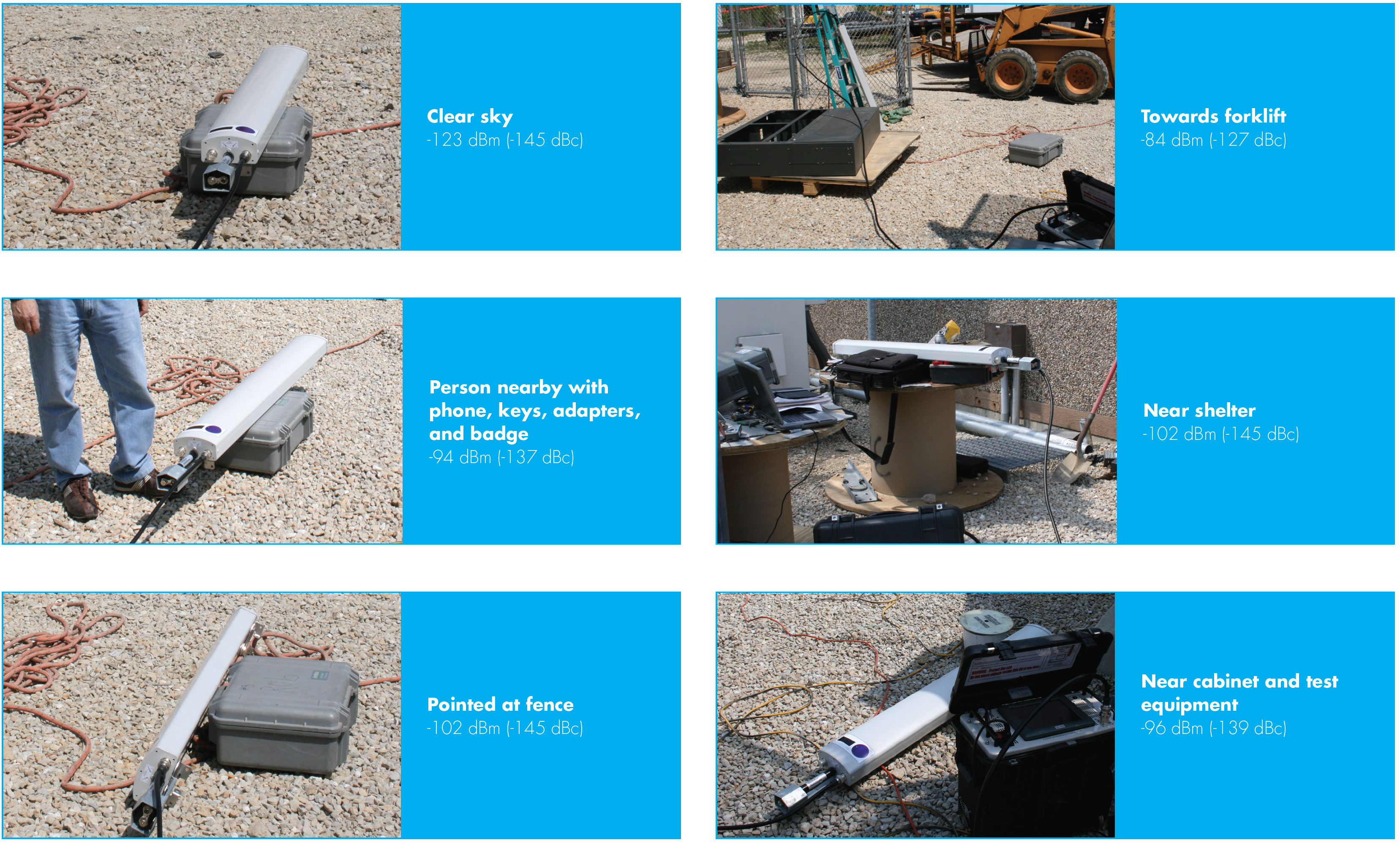 Figure 3: Testing for PIM can be challenging as objects in the environment can impact test results.
Using interference mitigation filters
An Interference Mitigation Filter (IMF) can be thought of as simply a filter in a gray box with a connector on each end. When you insert it in the RF path, interference is attenuated, or rejected, while the useful signal passes through with minimal attenuation.
But an IMF doesn’t have to be a stand-alone device. Thanks to the powerful modeling software we have today, an experienced designer can create almost any desired filter function. A multitude of RF conditioning products – tower mounted amplifiers (TMAs), multi-band combiners (MBCs) and same band combiners (SBCs) – can incorporate filters with different functions. We can think of an IMF not simply as a filter but as a function of a filter design. When creating a filter for a TMA, for example, IMF functionality can be incorporated along with the other requirements for this filter.TMAs, SBCs, and similar products are frequently designed around requirements that take into account common interference scenarios. The clear advantages of integrating IMF functionality into RF conditioning products come from miniaturization, simplification and innovation. The gray box is no longer needed. Overall performance can be improved when the combined filter functions are built and optimized together, and external connections are eliminated. When defining your requirements for any RF conditioning products, you should also consider your needs for interference mitigation.
What's next?
As MNOs seek to increase capacity in their networks, densification is a key strategy. However, densification increases interference concerns. But as we have seen, there are strategies and technologies available that reduce interference to create a high SNR, and with them the reliable, high-performance cellular services that subscribers demand.